Illuminating Connectivity: A Practical Guide to UniFi AP Antenna Radiation Patterns
Published by Juan David Ramirez on 20th Feb 2025
Hello everyone, Juan David here, your Tech Support Lead at Flytec. In today’s blog, I’ll walk you through the essentials of antenna radiation patterns in UniFi Access Points (UAPs). Understanding these patterns will help you optimize your wireless coverage, reduce interference, and ensure your network delivers the performance your clients or organization demand.
AP Antenna Radiation Patterns
Antenna radiation patterns essentially describe how an access point broadcasts (transmits) and receives wireless signals across its coverage area. The key term to remember here is reciprocal—the transmit power (how well the AP “speaks”) is highest at the strongest points of the antenna’s pattern and receive sensitivity (how well the AP “hears”) is likewise strongest at those same points.
A Word on Anechoic Environments
The radiation patterns you often see in official documentation or datasheets are gathered in anechoic (echo-free) chambers. Out in the real world though, your environment is filled with walls, furniture, equipment, and other reflective materials. These variables will alter the shape, peak gain, and overall efficiency of the signal.
For example, a signal passing through concrete walls might lose 20-40% of its strength, while drywall may result in a smaller loss of around 5-15%. Identifying these barriers before deployment can help you position APs more effectively.
Measuring is Key
While these radiation plots provide an excellent starting point, measurement is the final and most accurate way to verify your coverage design. Tools like the Ubiquiti WiFiman Wizard (WM-W) simplify this process, offering real-time insights to identify weak spots and optimize AP placement. Make a habit of measuring:
1. Before Installation (Mock Positioning)
Conduct a site survey or a predictive RF design using mock or temporary AP placements.
2. During Installation
Periodically test coverage as you finalize AP locations—ensuring no unexpected obstacles or reflections are hindering performance.
3. After Installation
Perform a final site survey to confirm you have the right coverage where you need it and minimal interference where you don’t (avoiding APs hearing each other too much on the same channel).
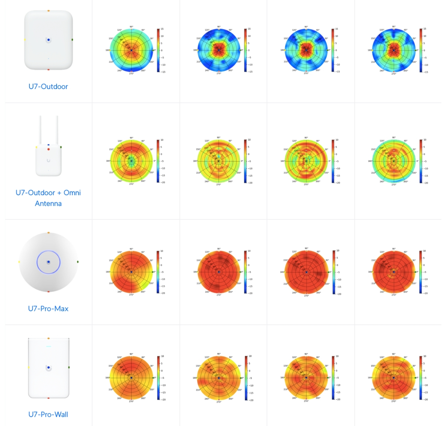
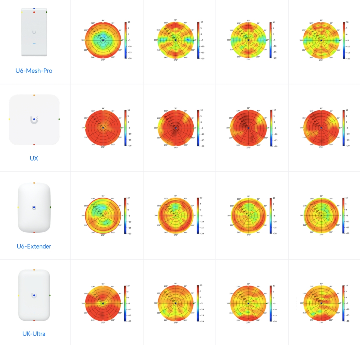
Comparison Table
Below, you’ll typically find a comparison table for different UniFi AP models. Each device might have color-coded points in its respective radiation plot. The first column of such a table helps map each color (or dot) to where it’s located on the physical device.
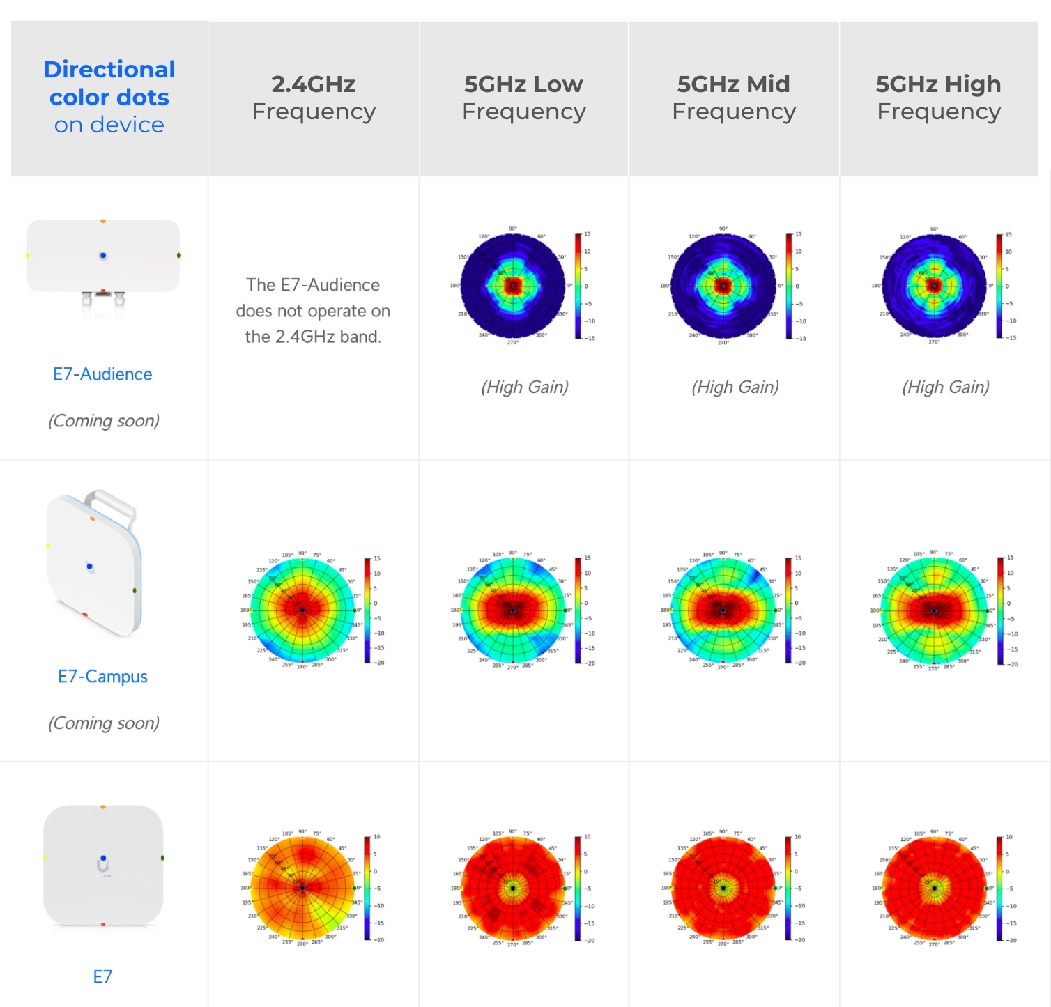
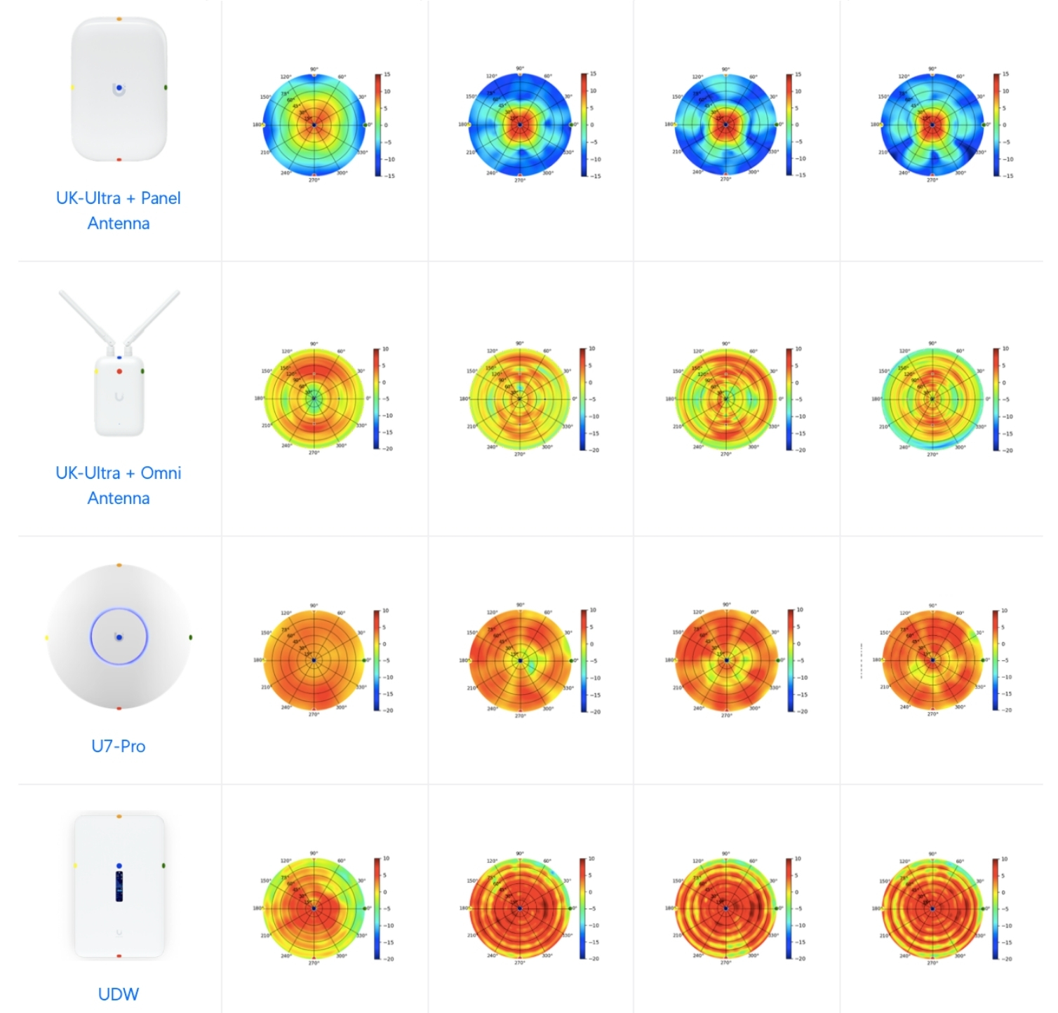
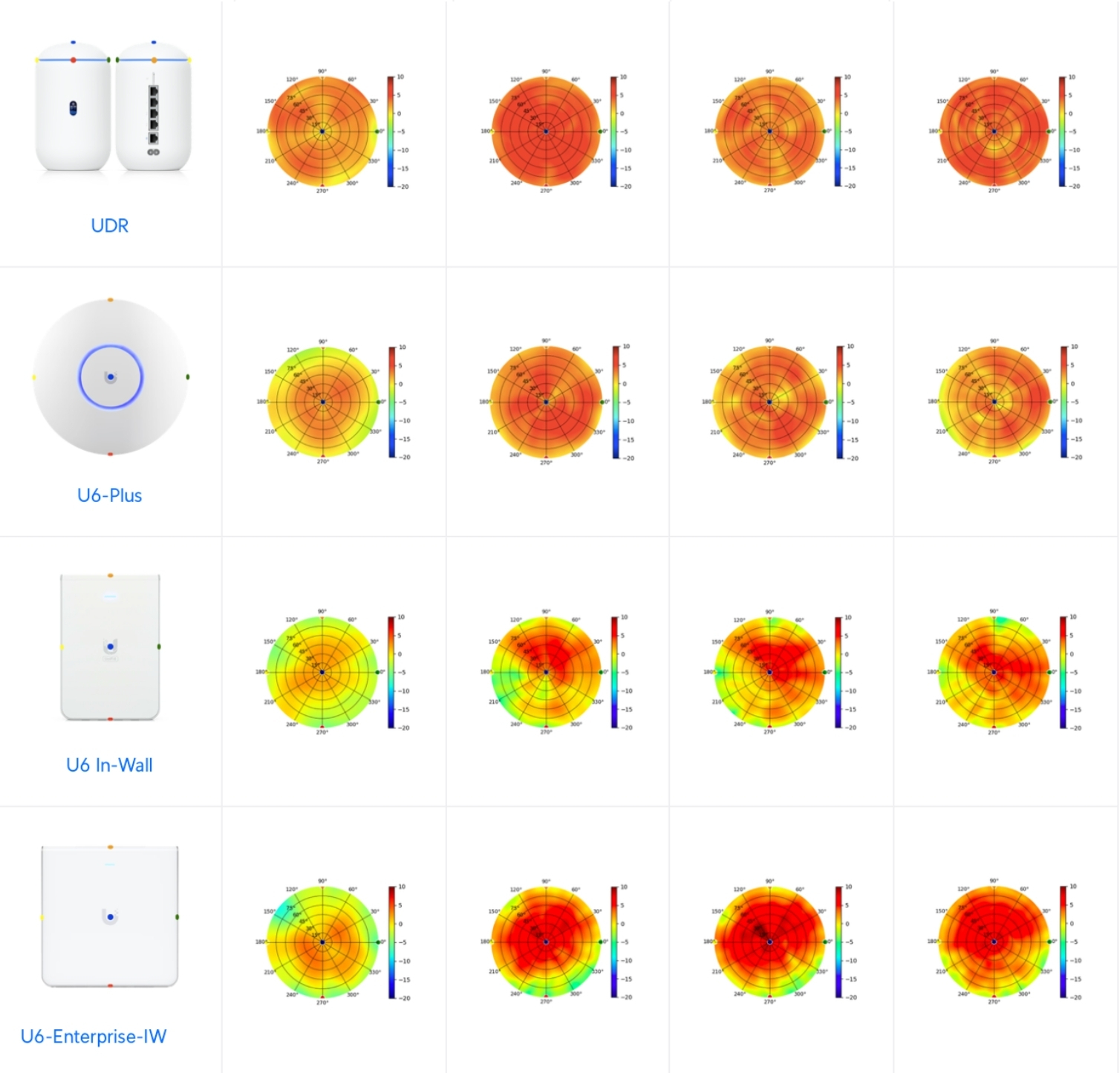
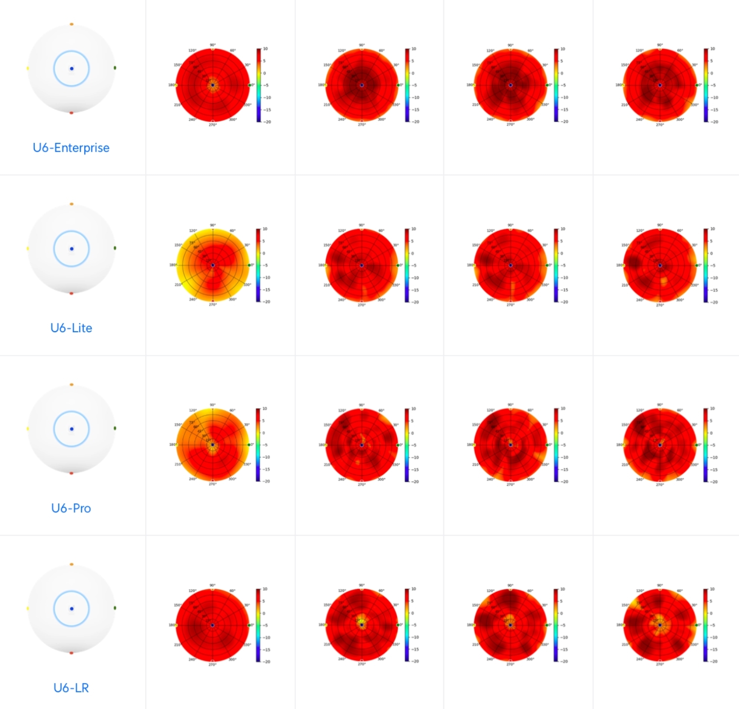
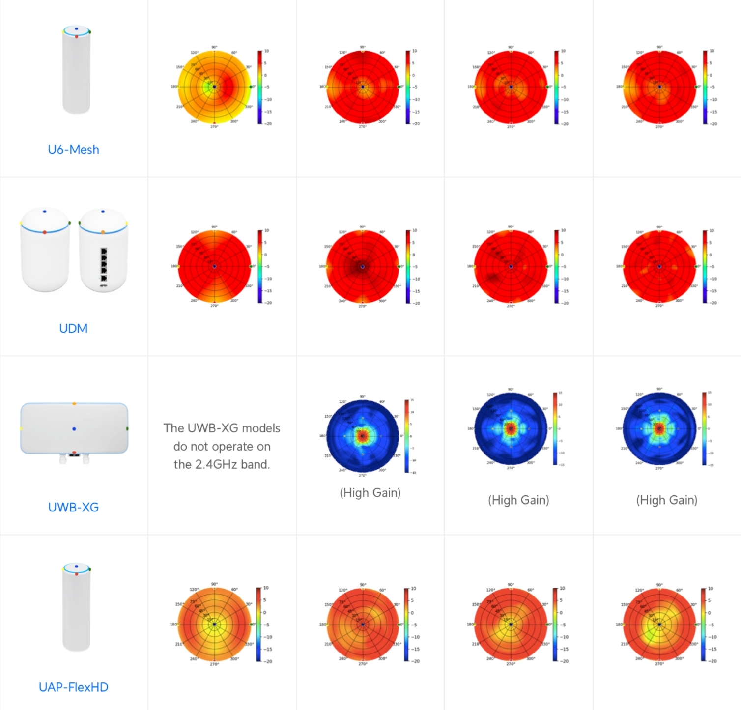
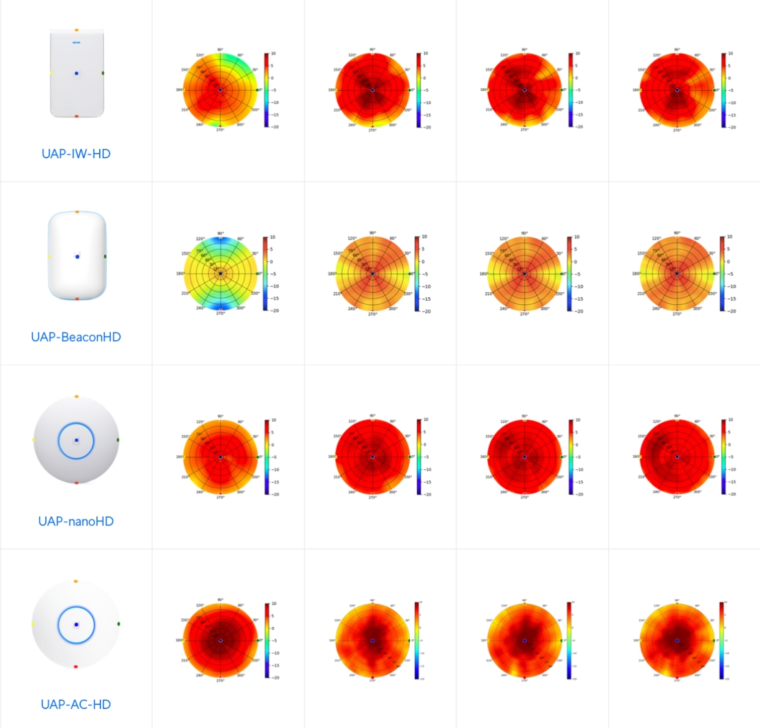
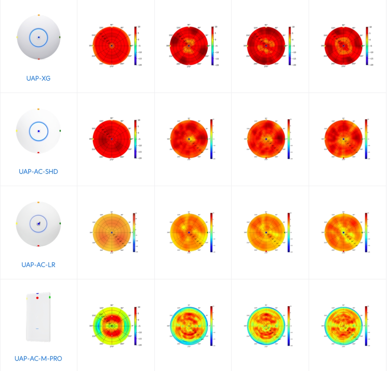
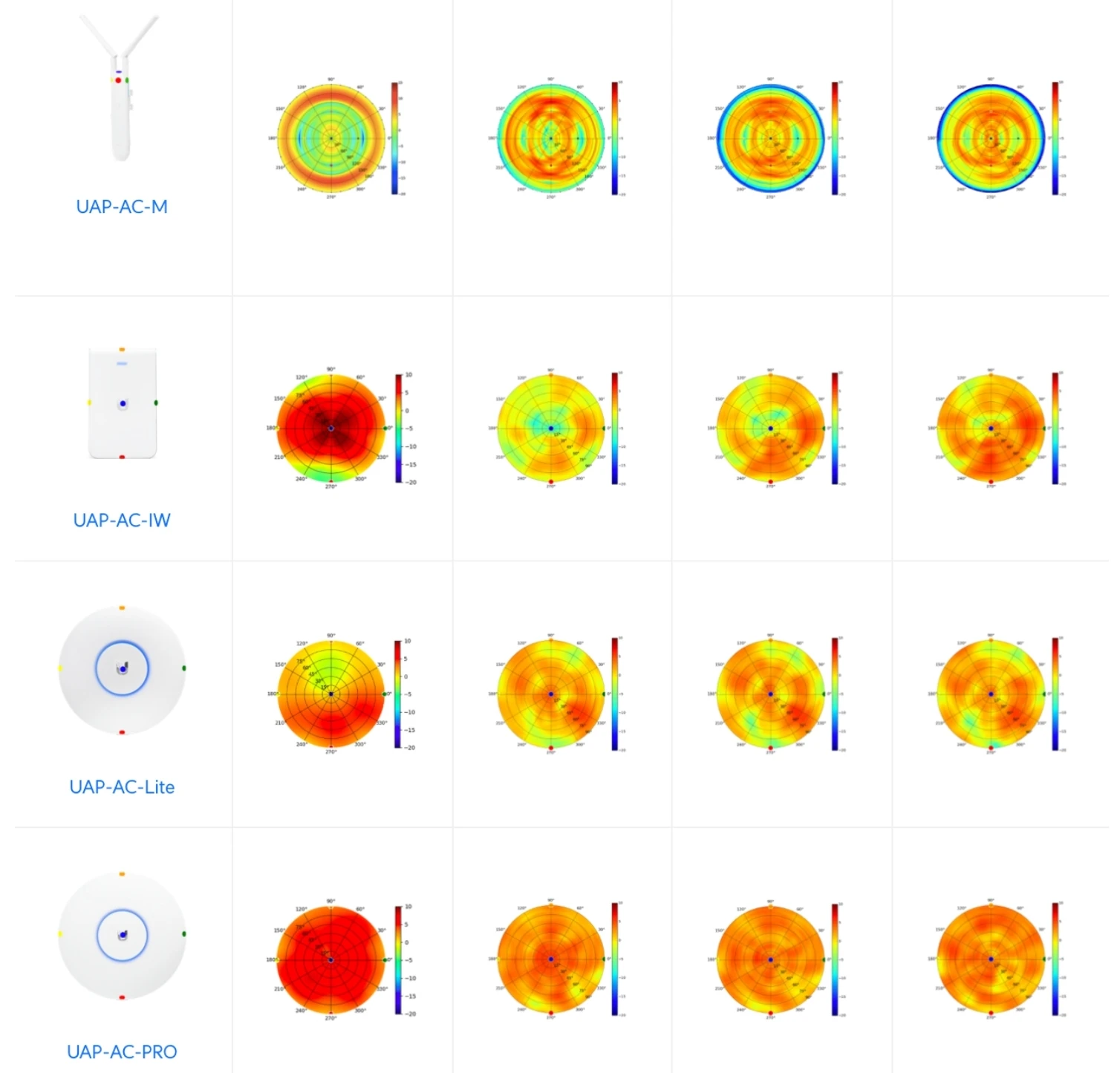
Keep in mind:
- The dots in the plots may appear on the outer perimeter or closer to the center, each corresponding to different antenna segments or orientations.
- Pay attention to varying scales—one model’s dB scale may differ from another, so compare them individually.
Use Cases and Best Practices
- Identify Key Coverage Areas: If you see strong peaks in one direction, aim that toward high-traffic zones.
- Limit Self-Interference: Overlapping AP coverage on the same channel can reduce performance. Adjust channel assignments and power settings accordingly.
- Account for Obstacles: Certain walls, metal racks, or even tinted glass can degrade signals. Consider their impact on coverage.
- Document and Test: Keep a record of your installation steps, the radiation patterns consulted, and all pre-/post-installation measurements.
When it comes to deploying a robust wireless network, understanding antenna radiation patterns is a critical piece of the puzzle. However, always remember that real-world measurement is the ultimate test. By using radiation plots as a reference and validating coverage through direct measurements, you’ll ensure the most reliable and efficient network for your environment.
Stay tuned for more insights into designing and optimizing UniFi networks. If you have any questions or need support, feel free to reach out!